For module 7 at the University of Twente (2nd year’s bachelor) the assignment was to research, analyse, design, and evaluate a de-icing system. One of the specifics of that assignment was to “Develop a numerical solver using regular coding that performs calculations in the velocity field of the flow around a cylinder.”
This page contains part of the fruits of that pursuit; namely the animations it was able to produce. Since PDF’s generally don’t carry animations very well or at all, they are placed here; along with some of the more “buggy” —but interesting— examples. This is obviously not part of the final report (this was written after the deadline), so it’s slightly less serious; but it would be a shame to not present these.
Initially work started on the mandatory part of the assignment. That went quite well; the core was written over a weekend. That resulted in something that looked like this1:
However, of course there were bugs2:
This particular example had an issue with the vorticity aspect of the potential flow equation; hence why the lower stream accelerates and the upper takes a significant detour. But in the end, those issues were ironed out:
Approximately at the same time, functionality was implemented which allowed droplets with different masses; which is also what is shown above. The larger and bluer the droplet; the higher it’s mass.
For the project, a practical in one of the University’s wind tunnels was also planned. Due to the SARS-CoV2 epidemic, this didn’t go ahead; but the simulation of the experiment was finished in time:
The plan was to examine the droplet path around a PVC pipe. The droplets were created by a vibrating needle (to break up the continuous stream), and to examine the path with a high speed camera.
As a bonus, the assignment mentioned also implementing a solution for wing profiles in addition to the cylinder. The idea was that this would be done in the final few weeks after all the analysis was performed based upon the cylinder; but since implementing the cylinder went so well the Joukowski transform was implemented immediately thereafter.
This went slightly less well, in particular with respect to the inverse transform. This inverse was required due to the way the simulator’s core was implemented, and it could thus not be avoided. Thanks to a particularly knowledgeable student assistant, the final few issues were resolved. The bugs in the inverse transformation, before those bugs were resolved, lead to results such as shown below3:
Another encountered bug was the combination of a slightly off drag coefficient and droplets which were a million times to heavy due badly chosen input parameters:
Yes, they all just go straight ahead; and yes, some just teleport through the trailing edge. This latter issue is due to the timestep of the simulation being too large for the velocity of the particles; so some have enough speed to jump over the trailing edge without ever being filtered out by the collision detection. Again, in the end these issues were resolved:
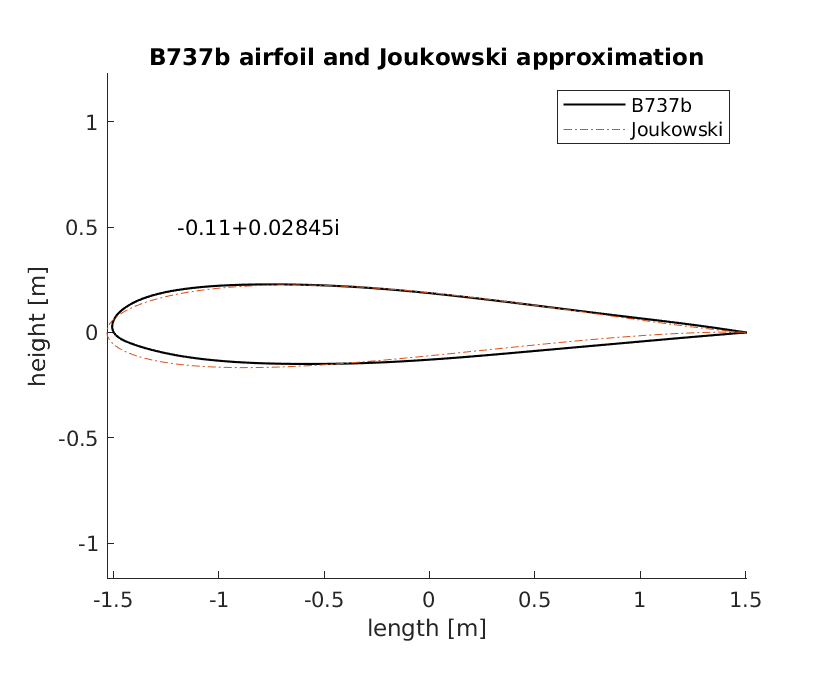
For the project itself, the airfoil of the 737 was used (or rather approximated), leading to a somewhat flatter airfoil than the one used for tests; which, while visually less interesting, was more applicable to the project itself:
While the airflow around a cylinder can be considered to be similar to the airflow around an airfoil (see the Magnus effect, for example); this does not hold for particles therein. Due to their inertia, they don’t follow the path the fluid they’re contained in exactly; and thus the geometry of the object which causes the disturbance in the airflow is important.
While streams of random droplets certainly look nice; the paths they take are also relevant.
In these plots, the position of each particle is tracked externally from the simulator core (it doesn’t safe this information itself). Those stored locations form the line. As with the earlier animations, the larger and bluer the particle, how heavier it is. In this case, the velocity vector of each droplet is also drawn. Finally, where droplets impact, a cross appears on the surface of the object.
From these animations it is especially evident that heavier droplets are less influenced by the airflow; while the lighter droplets tend to follow the contours of the object.
Moreover, as mentioned in the previous section, the geometry of the object is very important for the path the droplets take. Compare, for example, the first and latter two animations below. In case of the cylinder, the droplets impact only very close to the leading edge (or the stagnation point)4; while for the airfoils the impact area is far wider.
In the section of the report which analysed the impact locations of droplets, five scenarios were analysed, namely at cruise speed and altitude (or in this case density):
while maneuvring at slightly negative, and positive angles of attack;
and finally at higher angles of attack for long final,
and short final:
avi instead of gif as an intermediate format.
[return]